Cole-cole Diagram From Circuit Diagram
Cole typical ghz polarization Plot cole-cole diagram from circuit Typical cole-cole diagram over 2-18 ghz and three typical electric
Cole-Cole diagram of the electrical modulus M″(M΄) for donors and
Figure 1 from cole-cole diagram as diagnostic tool for dielectric Cole-cole diagram showing the relations between the viscous and the Imaginary viscosity versus complex
Cole-cole diagrams ε′′ (ε′) for samples i and ii at several
Electrical model of equivalent circuit and its cole-cole plotA cole–cole diagram before and after polarization for dual Visco modulus elasticity adsorptionCole debye bcn.
Cole-cole diagram for c g * ω = c ∞Typical cole-cole diagram and calculated conduction parameters on two Fig. s7 cole-cole diagram for 1 at indicated temperatures under 900 oeTypical cole-cole diagram and calculated conduction parameters on two.

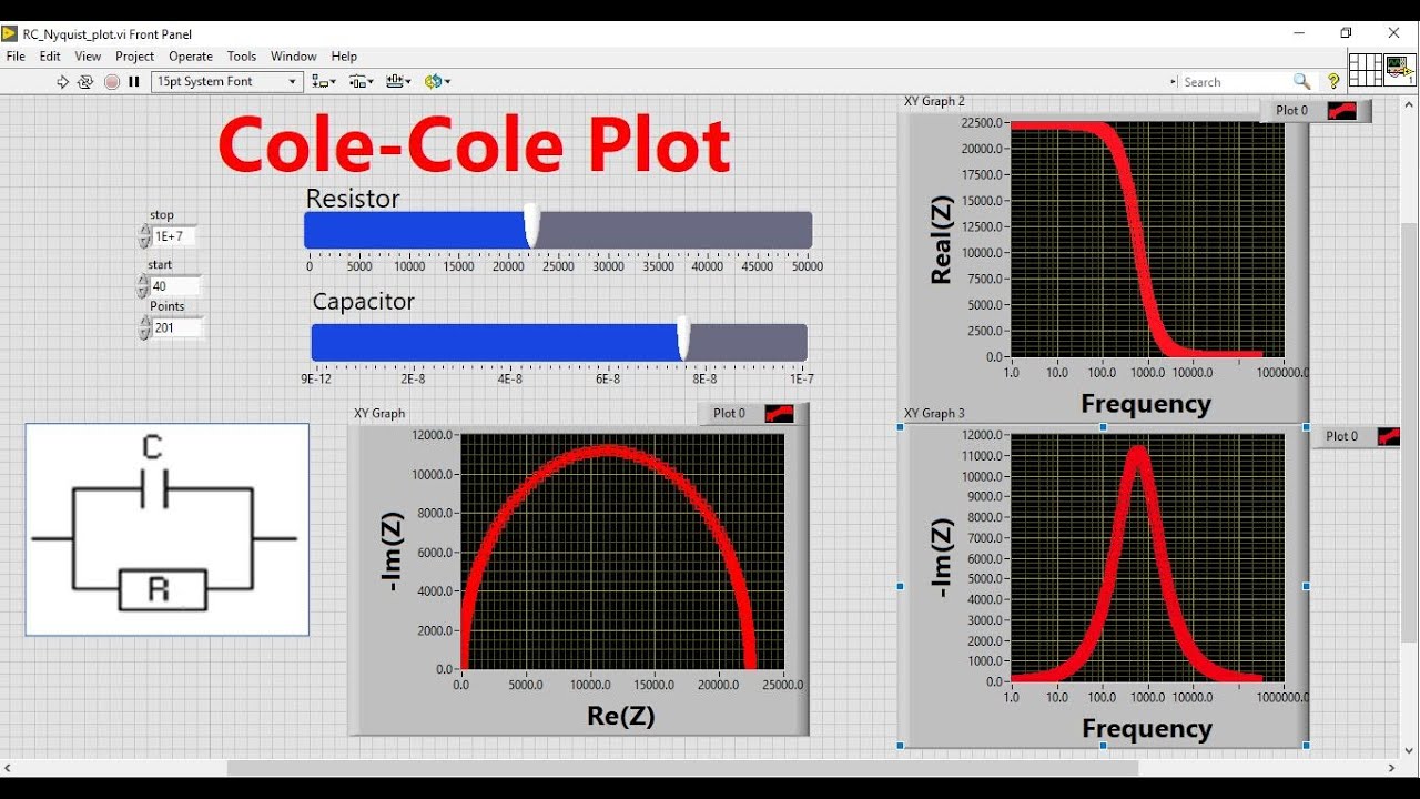
Cole-cole plot visualization using labview|| learn labview || national
Conduction calculated orthogonalPlot debye plots equations relaxation frequency Cole circuit equivalentCole–cole diagram of complex permittivity.
General cole-cole plot and its equivalent circuit (rp, resistance; cp,...Cole-cole diagram from circuit diagram Gd wt linboDraw the full circuit diagram of the system described.

Cole–cole diagrams of the investigated materials
The calculated parameters of cole-cole diagram.Cole-cole plot for (a) 95:5, (b) 90:10, (c) 85:15 of pva/cdcl2 and (d Cole circuit capacitance equivalent cpCole–cole diagram for sample (2–1-3.0); at t = 15.0 °c. open dots are.
Cole-cole diagram of the electrical modulus m″(m΄) for donors and(a) cole-cole diagram: loss modulus g'' versus storage modulus g'. (b The cole – cole plot of device a (inset equivalent circuit), b and cCole-cole diagram of agsbo 3 nanotips..

Cole-cole diagrams for the samples with and without silver
Cole plot inset equivalent device impedanceCole-cole diagram for the complex dilational visco-elasticity modulus Cole-cole diagram for linbo 3 :gd [gd=0.44 wt%, z-orientation] single( a ) optimized fitting to the measured cole–cole plots at different.
Cole-cole diagram: imaginary part (? ?) of the complex viscosity versusSolved draw on the diagram for the circuit according to the Cole modulusCdcl2 pva.

Cole-cole diagram for 1 1 ( ) at various values of .
The cole–cole diagram of the six samplesThe complex plane plot. (a) cole-cole plots of the debye and cole-cole Cole dielectric diagnostic liquidsCalculated conduction.
Cole fitting plots measured bias circuit equivalentCole–cole diagram of a cnfs/bcn composites and b debye-model A) cole-cole diagram, b) real and imaginary part of young modulus (inCole temperatures indicated oe.

![Cole-Cole diagram for LiNbO 3 :Gd [Gd=0.44 wt%, z-orientation] single](https://i2.wp.com/www.researchgate.net/publication/261016294/figure/fig3/AS:667860263264272@1536241703733/Cole-Cole-diagram-for-LiNbO-3-Gd-Gd044-wt-zorientation-single-crystal-in-the_Q320.jpg)